
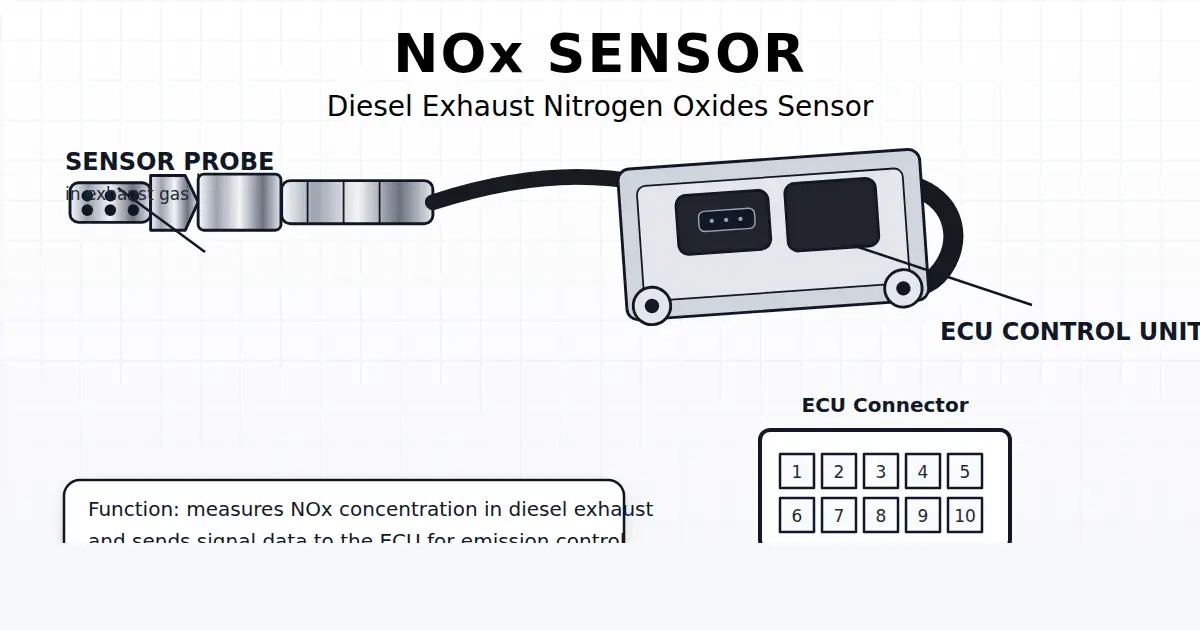
Understanding Heavy-Duty Diesel NOx Sensors: Intake vs. Outlet Operation
Modern diesel emission systems utilize two specialized Nitrogen Oxide (NOx) sensors to maintain closed-loop SCR control and comply with stringent EPA 10 / Euro 6 emissions targets:
- Upstream / Intake NOx Sensor (SPN 3216): Mounted in the turbocharger exhaust downpipe ahead of the Diesel Oxidation Catalyst (DOC) and Diesel Particulate Filter (DPF). It measures raw engine-out NOx output, enabling the ECM to calculate exact urea (AdBlue) dosing volume.
- Downstream / Outlet NOx Sensor (SPN 3226): Installed at the tailpipe exit behind the SCR catalyst and Ammonia Slip Catalyst (ASC). It verifies SCR conversion efficiency (target: >95% NOx reduction). If tailpipe NOx exceeds permitted thresholds, the ECM flags an emissions failure.
How the Ceramic Electrochemical Sensing Chamber Works
Inside the stainless steel tip lies a specialized multi-layer Zirconia (ZrO2) ceramic element containing two micro-cavities:
- First Chamber (Oxygen Pumping): Exhaust gas diffuses into the first chamber through a porous diffusion barrier. An internal electrochemical pump cell extracts oxygen molecules (O2) from the sample gas until oxygen partial pressure drops to near-zero, without decomposing NOx.
- Second Chamber (NOx Decomposition & Measurement): The oxygen-free gas passes into the second chamber, where a rhodium/platinum catalytic electrode dissociates NOx molecules into N2 and O2. The liberated oxygen ions are pumped across an electrolyte membrane, generating a minute nano-ampere (nA) current directly proportional to exhaust NOx concentration (0 to 3000 ppm).
Deciphering Common NOx Sensor Fault Codes
| SPN Code | FMI | Description | Primary Root Cause |
|---|---|---|---|
| SPN 3216 | FMI 5 | Aftertreatment 1 Intake NOx Sensor – Current Below Normal / Open Circuit | Heater element circuit broken; fractured wiring harness; damaged connector pins. |
| SPN 3216 | FMI 9 | Intake NOx Sensor – Abnormal Update Rate (CAN Timeout) | Sensor control unit (puck) lost power, ground, or CAN bus communication with engine ECM. |
| SPN 3226 | FMI 13 | Outlet NOx Sensor – Out of Calibration | Ceramic element poisoned by unburned engine oil (phosphorus/zinc), coolant silica, or heavy soot masking. |
| SPN 3226 | FMI 20 | Outlet NOx Sensor – Drift High (Under-performing SCR) | Failed urea dosing pump, clogged DEF injector nozzle, or degraded SCR catalyst substrate. |
Workshop Bench & Pinout Testing Procedures
When a diagnostic scanner flags SPN 3216 or SPN 3226, follow these physical bench tests before buying replacement sensors:
1. Supply Voltage & Ground Verification
Unplug the 4-pin or 5-pin sensor harness connector with the key ON, engine OFF. Using a digital multimeter:
- Pin 1 (Battery Positive): Must read full vehicle system voltage (11.8V to 14.2V for 12V systems; 23.5V to 28.4V for 24V commercial trucks). If voltage drops below 11.5V under load, trace supply relays and inline fuses.
- Pin 2 (Chassis Ground): Measure voltage drop from Pin 2 to chassis battery negative. Voltage drop must be less than 0.15V. Clean any rusted frame grounding studs.
- Pins 3 & 4 (CAN High / CAN Low): Measure DC voltage to ground. CAN High should read approximately 2.6V – 2.8V; CAN Low should read approximately 2.2V – 2.4V. Across Pins 3 and 4 with the battery disconnected, resistance must read approximately 60Ω (reflecting dual 120Ω terminating resistors).
2. Inspecting Ceramic Tip Poisoning
Carefully unscrew the sensor from the exhaust bung (M20x1.5 or M22x1.5 thread). Inspect the protective stainless steel cap:
- Black Soot Crust: Indicates recurring DPF face plugging, boost air leaks, or leaking common rail fuel injectors. Blow away dry carbon with clean shop air; never spray brake cleaner or solvent into the sensor tip.
- White / Crystalline Ash: Indicates engine coolant entering the combustion chamber (blown head gasket or EGR cooler leak). Coolant silicates permanently glaze the zirconia ceramic pores, requiring sensor replacement.
- Wet Oil Residue: Indicates turbocharger oil seal failure or worn valve guides. Oil burns onto the ceramic and permanently destroys the catalytic electrodes.
Why SHR Autoparts NOx Sensors Deliver True OE Reliability
Unlike cheap trading-company knockoffs that burn out in weeks, SHR Autoparts NOx sensors are engineered with:
- High-density alumina/zirconia co-fired ceramic elements resistant to thermal shock and moisture droplets.
- Automotive-grade microcontrollers with factory-calibrated PPM lookup tables matching Cummins, Detroit Diesel, PACCAR, Volvo, DAF, Scania, and Mercedes-Benz original ECM protocols.
- Hermetically laser-welded stainless steel sensor puck enclosures that resist underbody gravel impact and pressure washing.
Browse our extensive inventory of Heavy-Duty NOx Sensors or send your OE numbers to our sales engineers via our Instant RFQ Portal.
NOx Sensor Solutions
Continue from this guide to NOx sensor cross-reference, application support, and RFQ-ready product sourcing.
Need OEM cross-reference or wholesale pricing?
Send part numbers, applications, or sourcing requirements to SHR Autoparts for a faster B2B response.